Remove the system I/O board
Follow instructions in this section to remove the system I/O board.
About this task
This task must be operated by trained technicians that are certified by Lenovo Service. Do not attempt to remove or install the part without proper training and qualification.
When removing the memory modules, label the slot number on each memory module, remove all the memory modules from the system board assembly, and set them aside on a static-protective surface for reinstallation.
When disconnecting cables, make a list of each cable and record the connectors the cable is connected to, and use the record as a cabling checklist after installing the new system board assembly.
When the server has an LACM module (close-loop cooling module) installed, you must apply for a handle first if you need to install or remove the processor board, I/O board, and processor. However, while replacing the old LACM module with a new one, you do not need to apply for a handle as the new LACM module contains it.
Read Installation Guidelines and Safety inspection checklist to ensure that you work safely.
Power off the server and peripheral devices and disconnect the power cords and all external cables. See Power off the server.
Prevent exposure to static electricity, which might lead to system halt and loss of data, by keeping static-sensitive components in their static-protective packages until installation, and handling these devices with an electrostatic-discharge wrist strap or other grounding system.

The heat sinks and processors might be very hot. Turn off the server and wait several minutes to let the server cool before removing the server cover.
Procedure
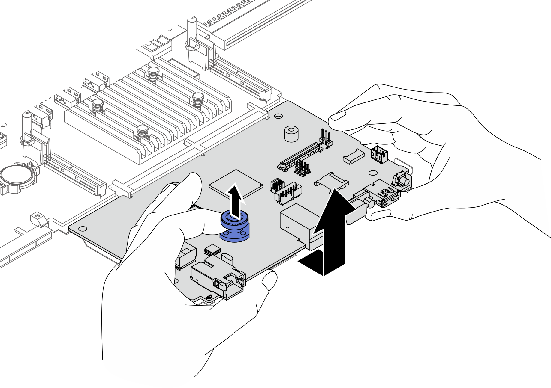
- Remove the system board assembly.Figure 1. System board assembly removal
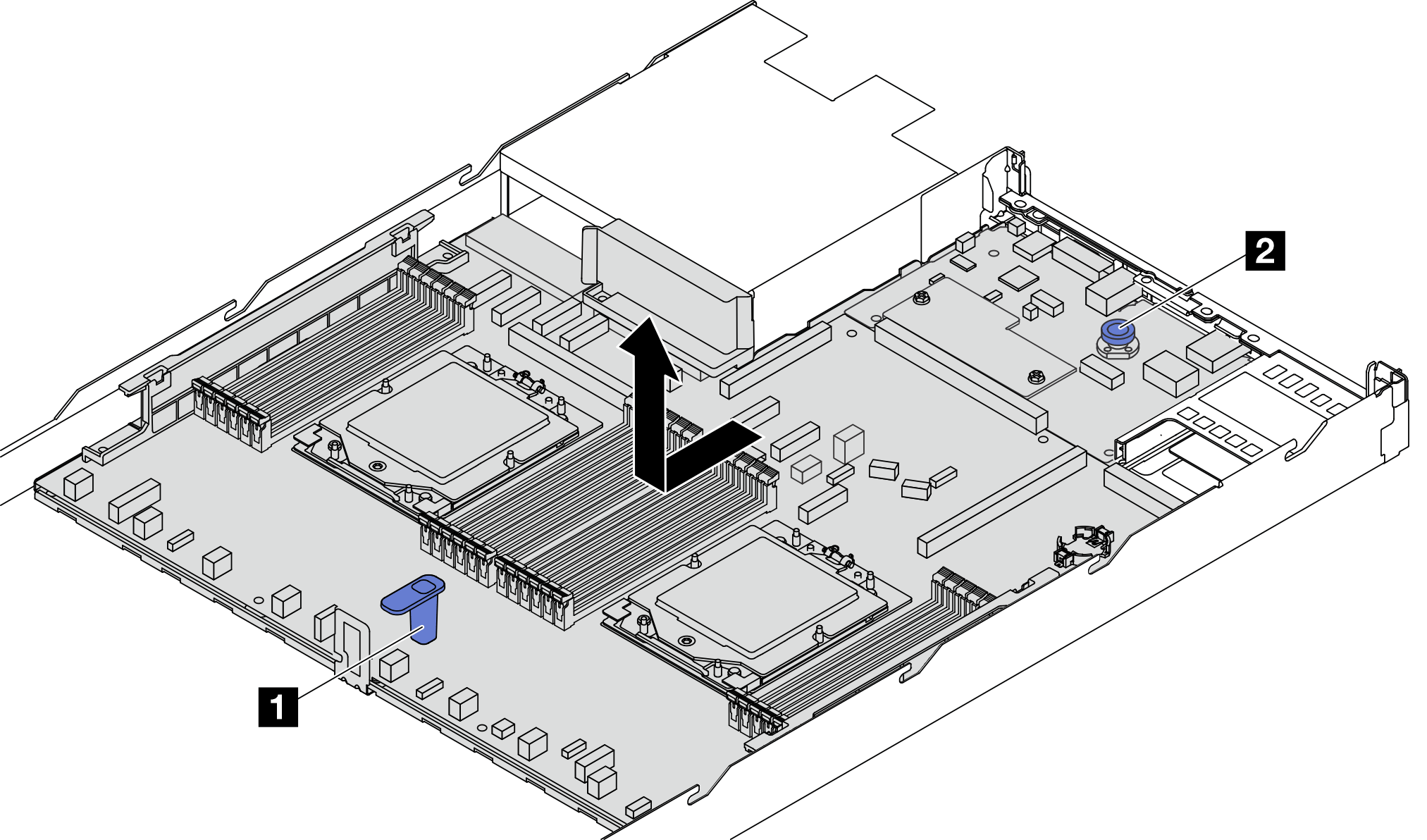
- Hold the lift handle 1 and lift the release pin 2 at the same time and slide the system board assembly toward the front of the server.
- Lift the system board assembly out of the chassis.
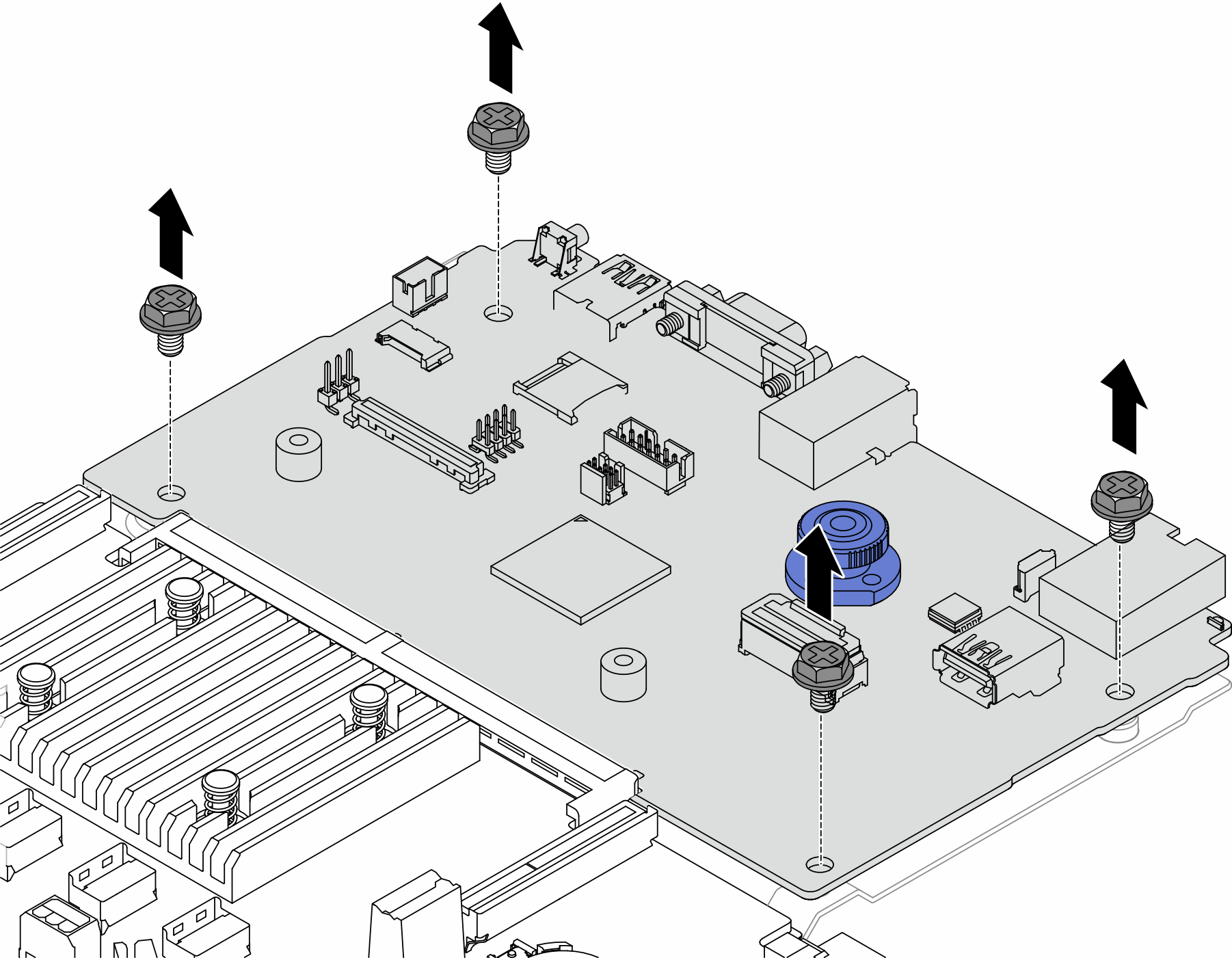
- Remove the screws that secure the system I/O board.Figure 2. Removing the screws
- Separate the system I/O board from the processor board.Figure 3. Separating the system I/O board from the processor board
- Remove the MicroSD card.Figure 4. Removing the MicroSD card
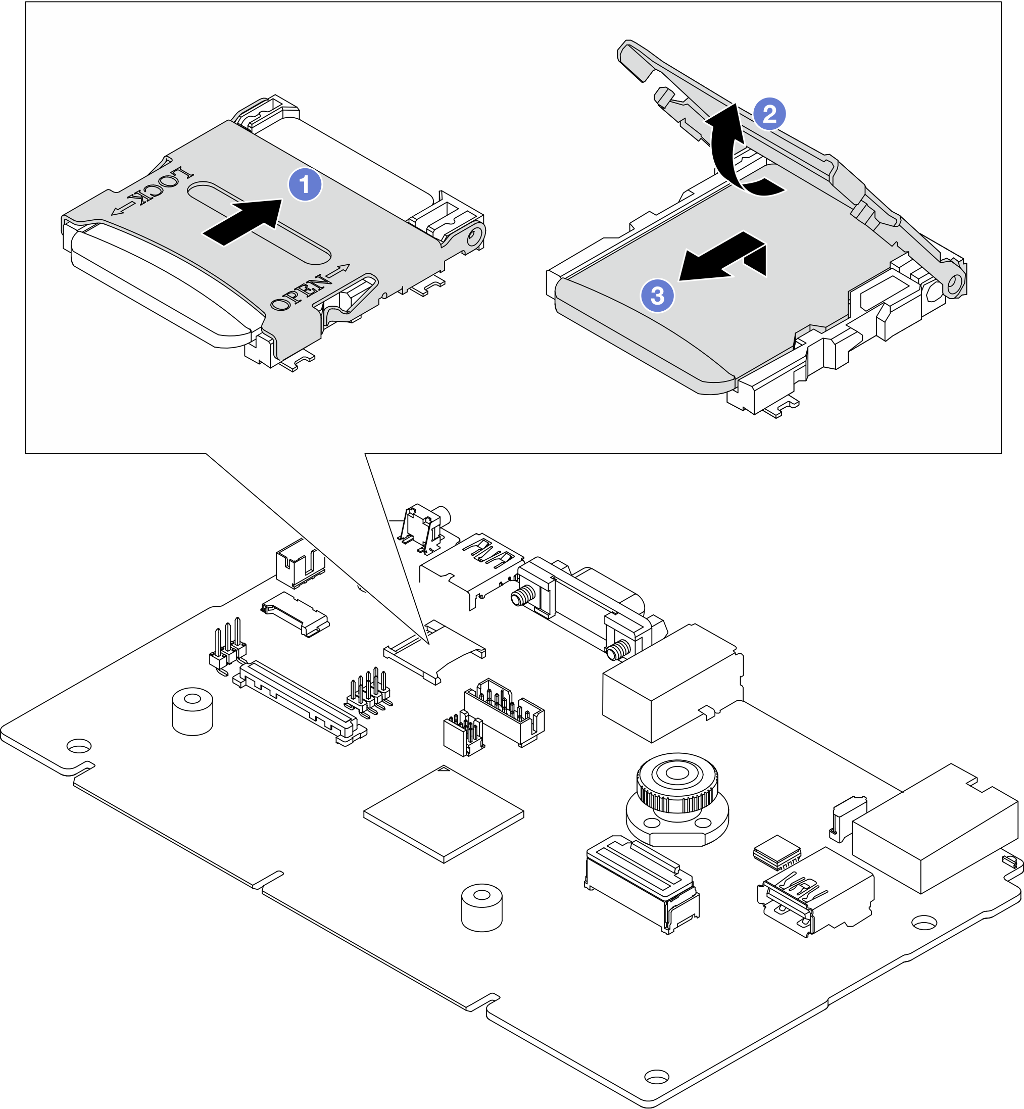
 Slide the shell to OPEN direction.
 Flip the socket hinge up.
 Remove the MicroSD card.
NoteAfter the MicroSD card is removed, the historical data of the firmware and user data uploaded through Remote Disc On Card (RDOC) will be lost, and the firmware rollback function and extended RDOC space will not be supported. To enable the two features, it will need to install a new MicroSD card.
After you finish
- If you are instructed to return the component or optional device, follow all packaging instructions, and use any packaging materials for shipping that are supplied to you.ImportantBefore you return the processor board, make sure that you install the processor socket covers from the new processor board. To replace a processor socket cover:
Slide the cover out from the processor socket of the new processor board.
Install the cover on the processor socket of the removed processor board.
If you plan to recycle the component, see Disassemble the system board (system board assembly) for recycle.
Demo video