Install the lower processor board (MB)
Follow instructions in this section to install the lower processor board (MB).
About this task
This task must be operated by trained technicians that are certified by Lenovo Service. Do not attempt to remove or install the part without proper training and qualification.
Read Installation Guidelines and Safety inspection checklist to ensure that you work safely.
Power off the server and peripheral devices, disconnect the power cords from the primary chassis, then disconnect the power cords from the secondary chassis. See Power off the server.
Prevent exposure to static electricity, which might lead to system halt and loss of data, by keeping static-sensitive components in their static-protective packages until installation, and handling these devices with an electrostatic-discharge wrist strap or other grounding system.
Go to Drivers and Software download website for ThinkSystem SR950 V3 to see the latest firmware and driver updates for your server.
Go to Update the firmware for more information on firmware updating tools.
Procedure
- Install the lower processor board (MB).Figure 1. Lower processor board (MB) installation
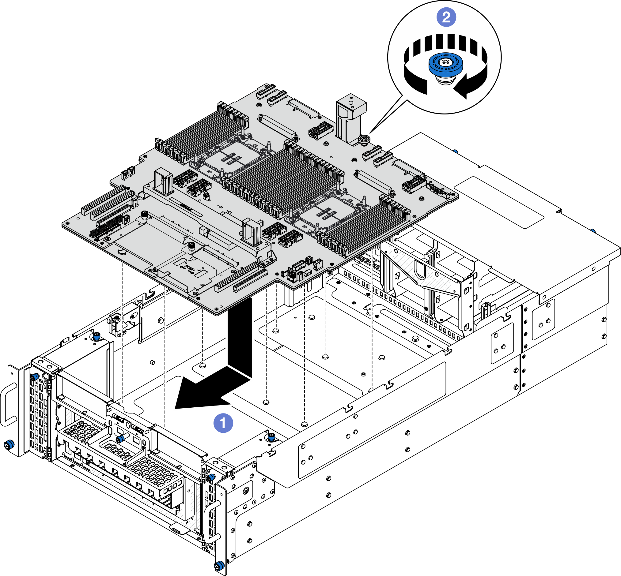
 Grasp the thumbscrew and lower processor board (MB) handle; then, lower the lower processor board (MB) into the chassis and slide it towards the front of the chassis.
  Tighten the thumbscrew to secure the lower processor board (MB). Use a screwdriver if needed.
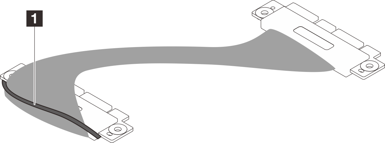
- For primary chassis only; if necessary, remove the 1 rubber band from the SCM cable.Figure 2. Removing SCM cable packaging
- For primary chassis only, connect the SCM cable.Figure 3. Connecting SCM cable
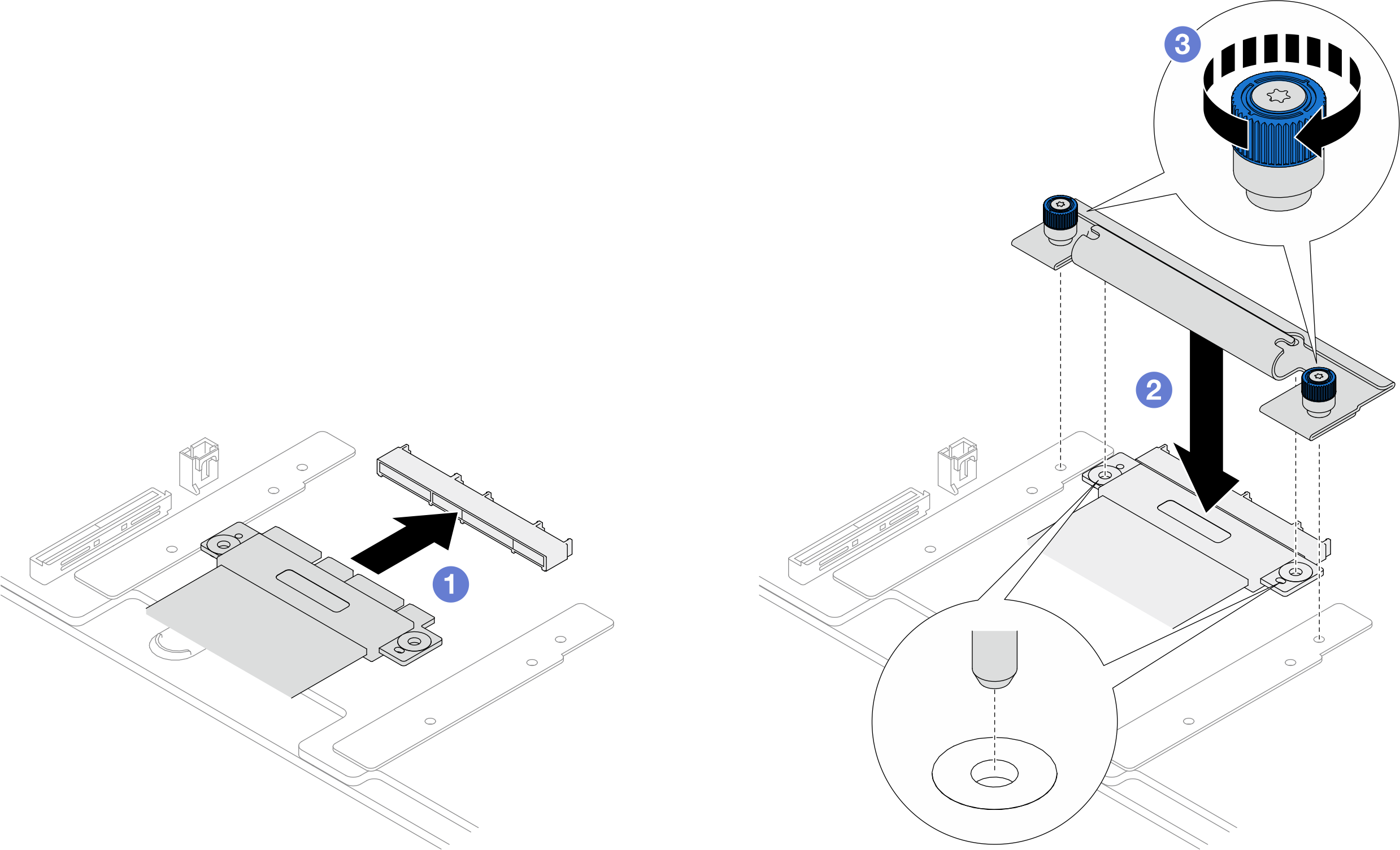
- Connect the SCM cable to the lower processor board (MB).
- Align the pins on the SCM bracket with the openings on the SCM cable; then, lower the SCM bracket onto the SCM cable.
- Tighten the two thumbscrews to secure the SCM cable. Use a screwdriver if needed.
- Connect the internal UPI cables to the lower processor board (MB).Figure 4. Connecting internal UPI cables
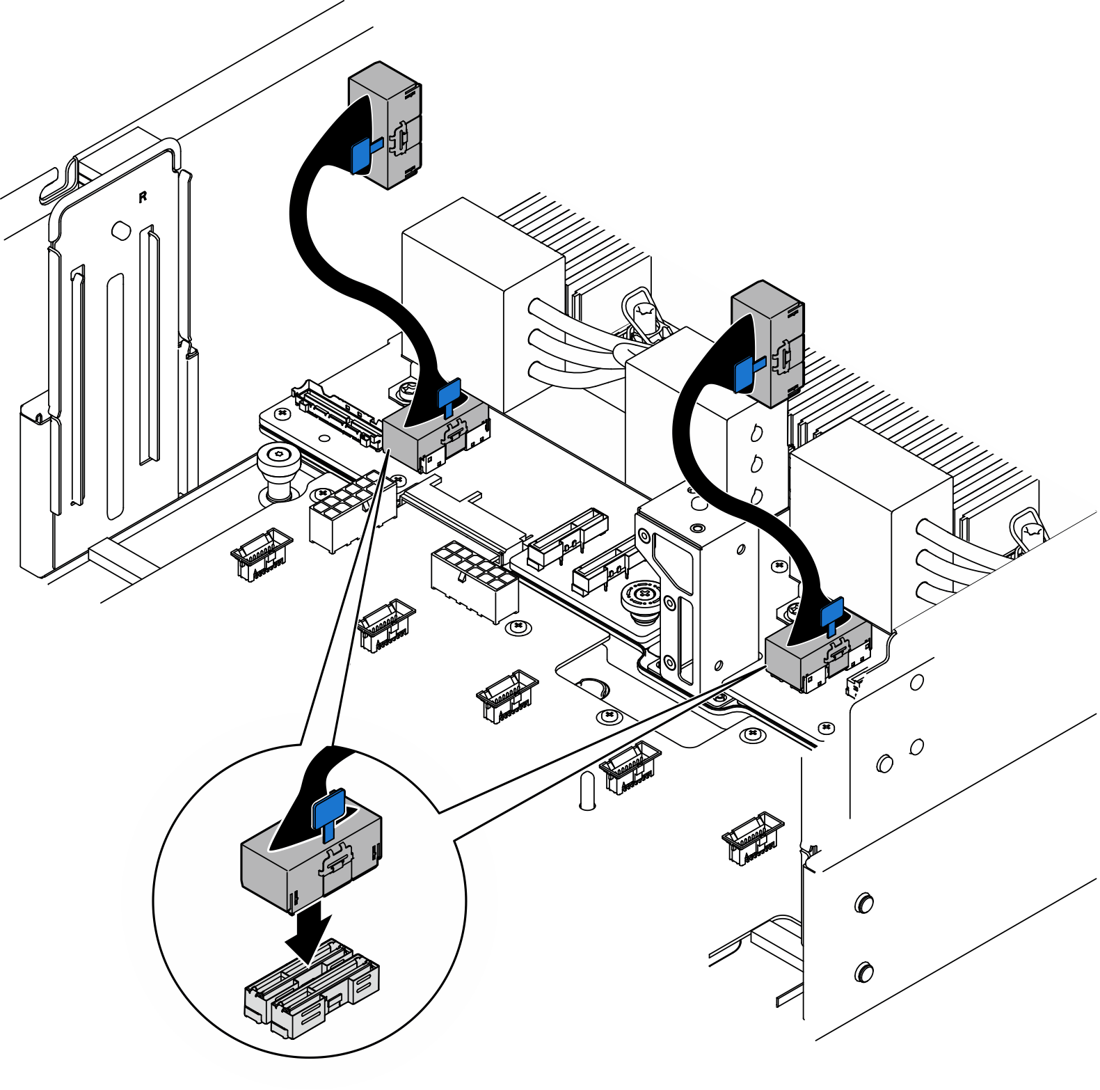
- Connect the UPI module cables.Figure 5. Connecting UPI module cables
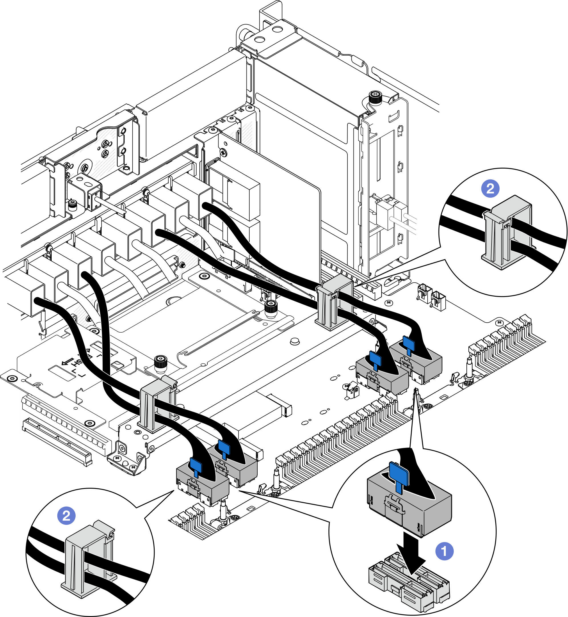
- Connect the UPI module cables to the lower processor board (MB).
- Route the UPI module cables through the cable clips and close them.
After you finish
Reinstall all PCIe adapters to the lower processor board (MB). See Install a PCIe adapter.
Reinstall all the M.2 drive to the lower processor board (MB). See Install an M.2 drive.
Install the MicroSD card. See Install the MicroSD card.
Install the sideband card. See Install the sideband card.
Reinstall the memory modules. See Install a memory module.
Reinstall the PHMs. See Install a processor and heat sink.
For primary chassis only, reinstall the system I/O board and interposer assembly. See Install the system I/O board and interposer board.
Reinstall the support bracket. See Install the support bracket.
For primary chassis only, reinstall the front operator panel and front operator panel cage. See Install the front operator panel.
Reinstall the lower processor board (MB) air baffle. See Install the lower processor board (MB) air baffle.
Reinstall the upper processor board (CPU BD). See Install the upper processor board (CPU BD).
Reinstall the upper processor board (CPU BD) air baffle. See Install the upper processor board (CPU BD) air baffle.
Reinstall the power distribution board. See Install the power distribution board.
Reinstall both power interposer boards. See Install the power interposer board.
Reinstall the fan cage. See Install the fan cage.
Reinstall the front top cover. See Install the front top cover.
Reinstall all the power supply units. See Install a hot-swap power supply unit.
Ensure that all components have been reassembled correctly and that no tools or loose screws are left inside the server.
- Reconnect the power cords to the secondary chassis, then reconnect the power cords to the primary chassis.NoteIt is recommended to connect PSU P1-P3/S1-S3 to a PDU different from PSU P4-P6/S4-S6 in case of PDU failure.
Power on the server and any peripheral devices. See Power on the server.
Complete the parts replacement. See Complete the parts replacement.
Demo video