Remove the lower processor board (MB)
Follow instructions in this section to remove the lower processor board (MB).
About this task
This task must be operated by trained technicians that are certified by Lenovo Service. Do not attempt to remove or install the part without proper training and qualification.
When removing the memory modules, label the slot number on each memory module, remove all the memory modules from the lower processor board (MB), and set them aside on a static-protective surface for reinstallation.
When disconnecting cables, make a list of each cable and record the connectors the cable is connected to, and use the record as a cabling checklist after installing the new lower processor board (MB).
Read Installation Guidelines and Safety inspection checklist to ensure that you work safely.
Power off the server and peripheral devices, disconnect the power cords from the primary chassis, then disconnect the power cords from the secondary chassis. See Power off the server.
Prevent exposure to static electricity, which might lead to system halt and loss of data, by keeping static-sensitive components in their static-protective packages until installation, and handling these devices with an electrostatic-discharge wrist strap or other grounding system.
If the server is installed in a rack, remove the server from the rack. See Remove the server from rails.
Procedure
- Disconnect UPI module cables.Figure 1. Disconnecting UPI module cables
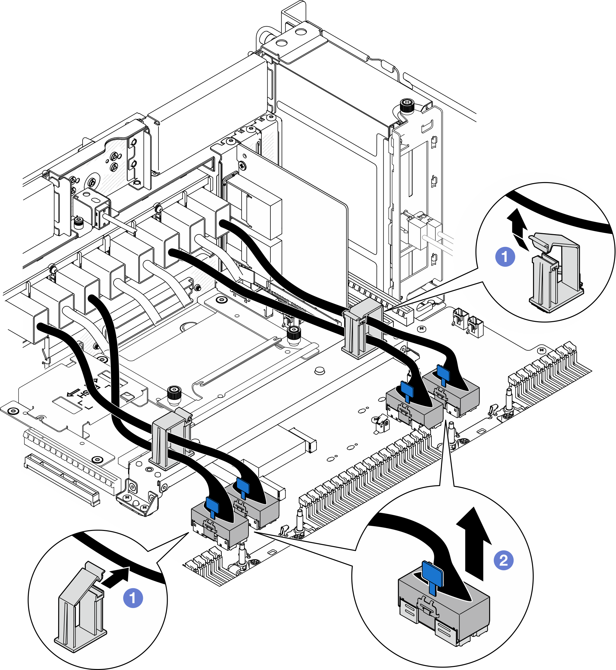
 Open the cable clips and unhook the UPI module cables.
 Disconnect the UPI module cables from the lower processor board (MB).
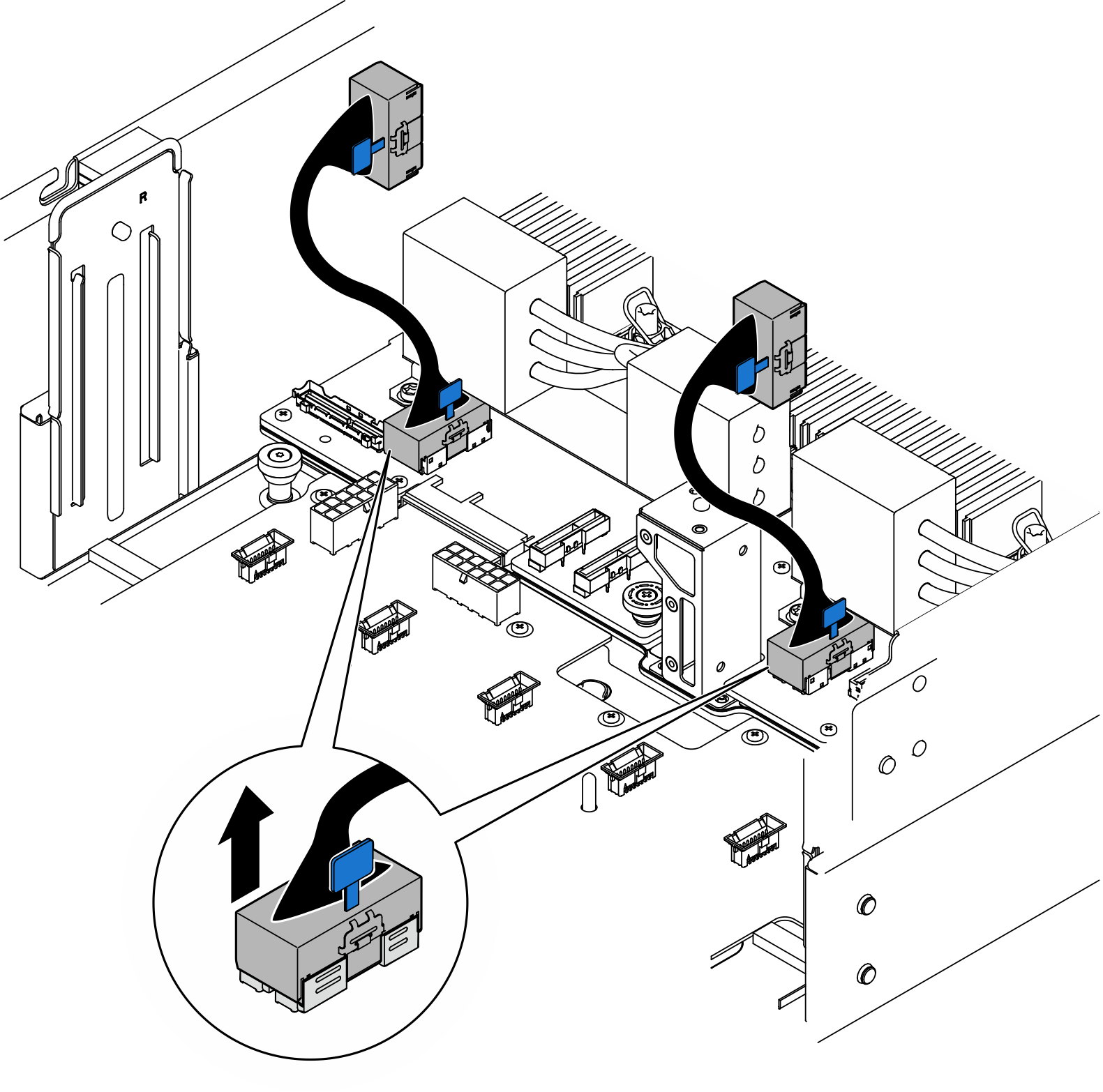
- Disconnect the internal UPI cables from the lower processor board (MB).Figure 2. Disconnecting internal UPI cables
- For primary chassis only, disconnect the SCM cable.Figure 3. Disconnecting SCM cable
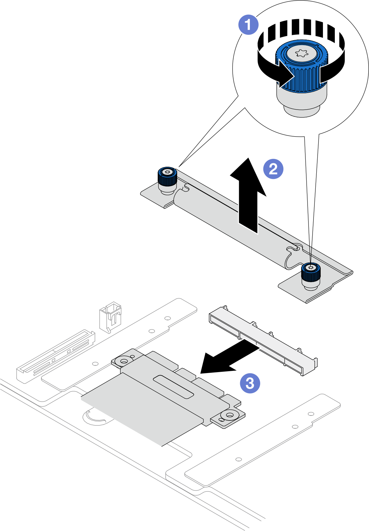
- Loosen the two thumbscrews on the SCM bracket. Use a screwdriver if needed.
- Remove the SCM bracket.
- Disconnect the SCM cable from the lower processor board (MB).
- Remove the lower processor board (MB).Figure 4. Lower processor board (MB) removal
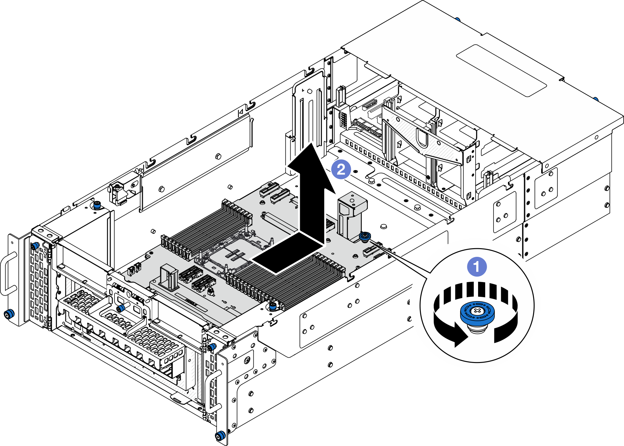 NoteThis lower processor board (MB) handle only serves the purpose of removing the lower processor board (MB). Do not attempt to lift the whole chassis with it.
- Loosen the thumbscrew that secures the lower processor board (MB). Use a screwdriver if needed.
- Grasp the thumbscrew and lower processor board (MB) handle; then, slide the lower processor board (MB) slightly towards the rear of the chassis to disengage and remove it.
After you finish
Install a replacement unit. See Install the lower processor board (MB).
If you are instructed to return the component or optional device, follow all packaging instructions, and use any packaging materials for shipping that are supplied to you.
ImportantBefore you return the lower processor board (MB), make sure that you install the processor socket covers from the new lower processor board (MB). To replace a processor socket cover:Take a socket cover from the processor socket assembly on the new lower processor board (MB) and orient it correctly above the processor socket assembly on the removed lower processor board (MB).
Gently press down the socket cover legs to the processor socket assembly, pressing on the edges to avoid damage to the socket pins. You might hear a click on the socket cover when it is securely attached.
Make sure that the socket cover is securely attached to the processor socket assembly.
If you plan to recycle the component, see Disassemble the lower processor board (MB) for recycle.
Demo video