Remove and replace the system-board assembly
- This procedure should be performed only by trained service technicians.
- If possible, back up all compute node settings, including the settings for any options installed in the compute node. To backup and restore system settings, see the Back up the compute node configuration Back up the compute node configuration for information and instructions.
Read Installation Guidelines to ensure that you work safely.
- If the compute node is installed in a chassis, remove it (see Remove a compute node for instructions).
- Carefully lay the replacement system-board assembly (system-board assembly FRU) and the defective system-board assembly (defective node) side-by-side on a flat, static-protective surface.
See System-board layout for more information about the locations of the connectors, switches, and LEDs on the system board.
To remove and replace the system-board assembly, complete the following steps:
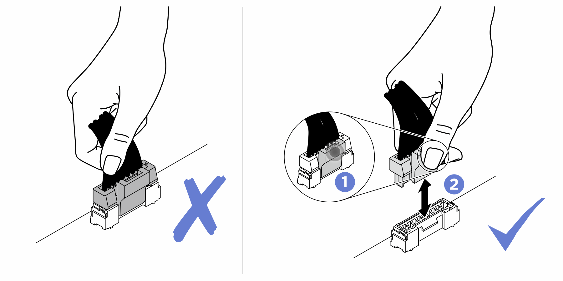
- If a RAID adapter is installed in the defective system-board assembly, remove it and set it aside on a static-protective surface (see Remove the RAID adapter for instructions).AttentionStrictly observe the following instructions to avoid damaging cable sockets on the system board. Any damage to the cable sockets might require replacing the system board.
Connect cable connectors vertically or horizontally in alignment with the orientations of the corresponding cable sockets, avoiding any tilt.
- To disconnect cables from the system board, do as follows:
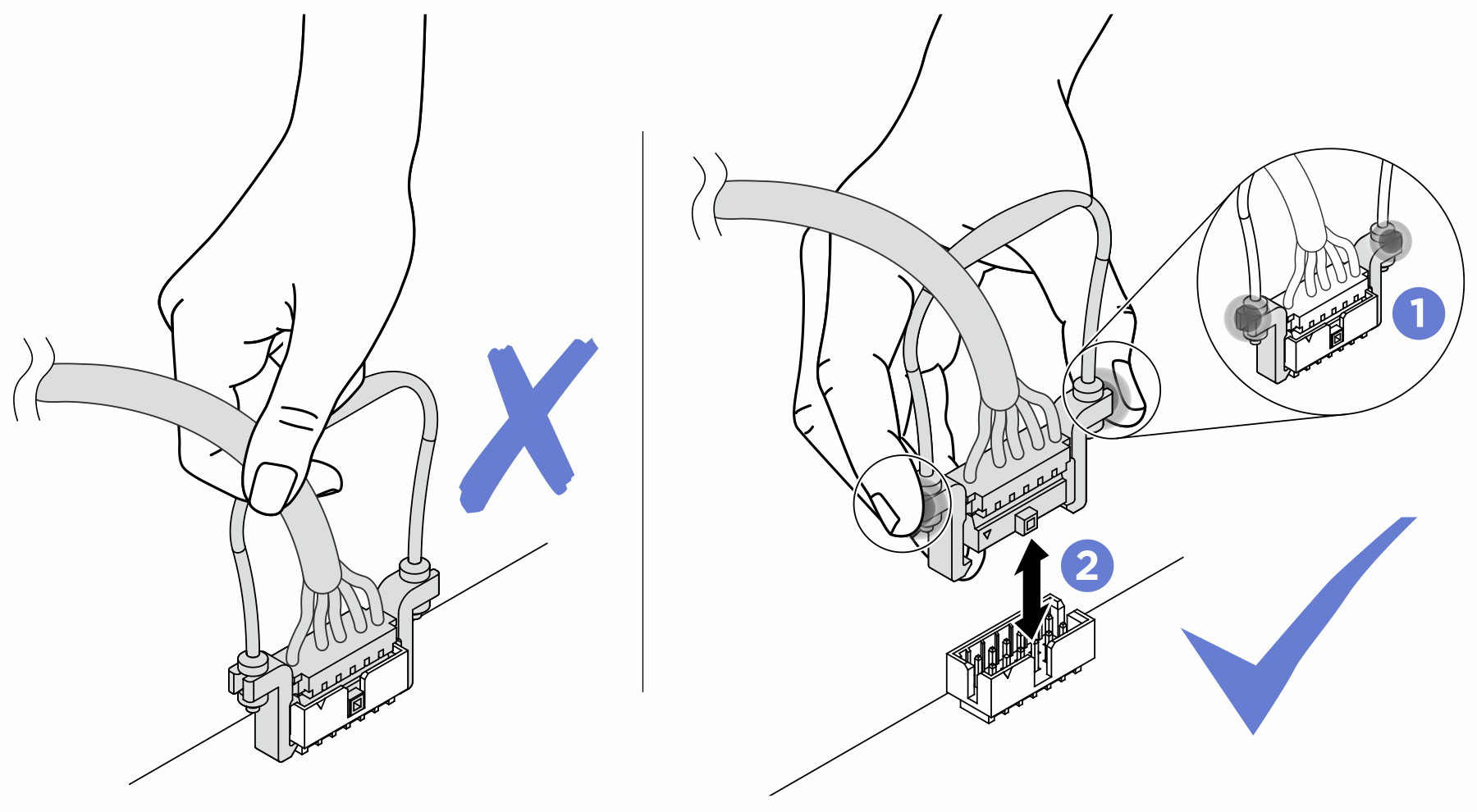
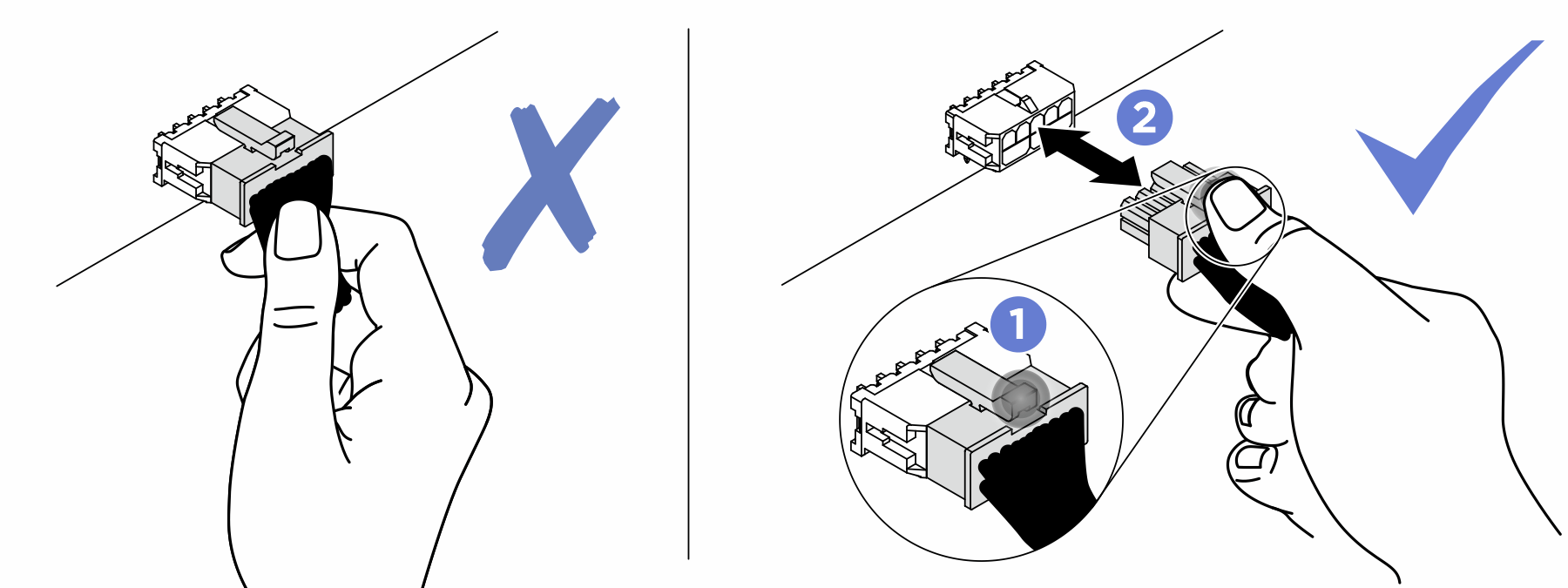
Press and hold all latches, release tabs, or locks on cable connectors to release the cable connectors.
- Remove the cable connectors vertically or horizontally in alignment with the orientations of the corresponding cable sockets, avoiding any tilt.NoteThe cable connectors might look different from those in the illustration, but the removal procedure is the same.
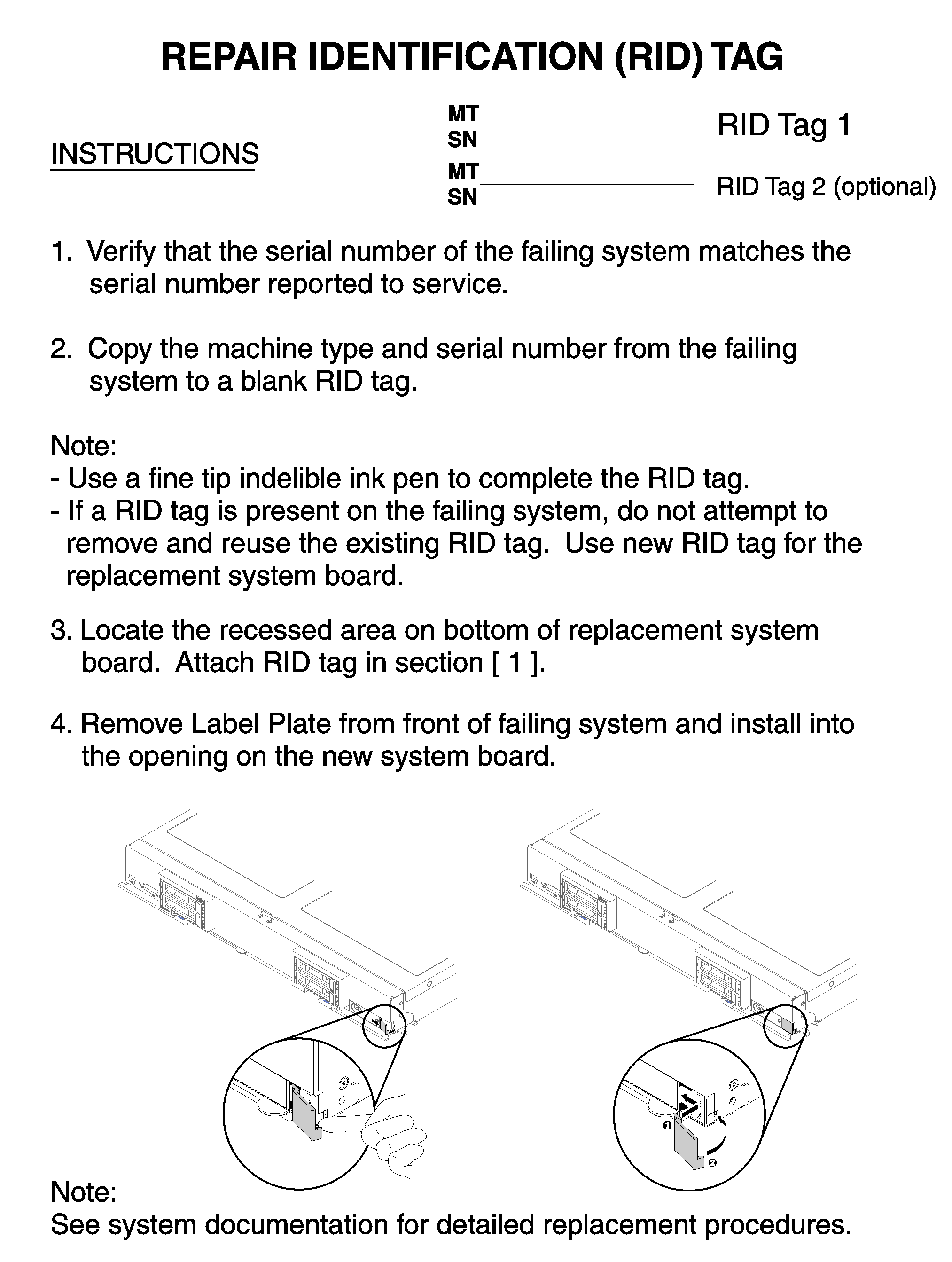
- The replacement system-board assembly comes with a Repair Identification (RID) tag. Using a fine tip indelible ink pen, transfer the machine type and serial number from the defective system-board assembly to the label on the Repair Identification tag; then, place the tag in the recessed area 1 on the bottom of replacement system-board assembly.Figure 1. Repair Identification (RID) tag
After you transfer components to the replacement system-board assembly, complete the following steps:
- Install the compute node in the chassis (see Install a compute node for instructions).
- If an Attention label is on the replacement system-board assembly front panel above the power button, read it; then, remove the label and discard it before turning on the compute node.
- Use the CMM Web Interface to restore the IP address of the compute node XClarity controller. See Starting the web interface for more information.NoteIf you configured static IP addresses, you will not be able to access the node remotely or from a management device until the IP addressLenovo XClarity Controller of the is restored.
Update the machine type and serial number with new vital product data (VPD). Use the Lenovo XClarity Provisioning Manager to update the machine type and serial number. See Update the machine type and serial number.
Enable TPM/TCM. See Enable TPM/TCM.
Optionally, enable Secure Boot (see Enable UEFI Secure Boot).
Update the compute node configuration.
Download and install the latest device drivers: Lenovo Data Center Support
Update the system firmware. See Firmware updates.
Update the UEFI configuration. See UEFI manual for ThinkSystem server.
Reconfigure the disk arrays if you have installed or removed a hot-swap drive or a RAID adapter. See the Lenovo XClarity Provisioning Manager User Guide, which is available for download at: Lenovo Data Center Support
Take a socket cover from the CPU socket assembly on the new system-board assembly and orient it correctly above the CPU socket assembly on the removed system-board assembly.
Gently press down the socket cover legs to the CPU socket assembly, pressing on the edges to avoid damage to the socket pins. You might hear a click on the socket cover is securely attached.
Make sure that the socket cover is securely attached to the CPU socket assembly.
If you are planning to recycle the system board, follow the instructions in Disassemble the system-board assembly for recycle for compliance with local regulations.
Demo video