Install a power distribution board cover
Follow the instructions in this section to install a power distribution board cover.
About this task
Read Installation Guidelines and Safety inspection checklist to ensure that you work safely.
Power off the server and disconnect all power cords for this task. See Power off the server.
Prevent exposure to static electricity, which might lead to system halt and loss of data, by keeping static-sensitive components in their static-protective packages until installation, and handling these devices with an electrostatic-discharge wrist strap or other grounding system.
Procedure
 Insert the power distribution board cover into place as shown.
 Tighten the captive screw to secure the power distribution board cover.Figure 1. Installation of a power distribution board cover
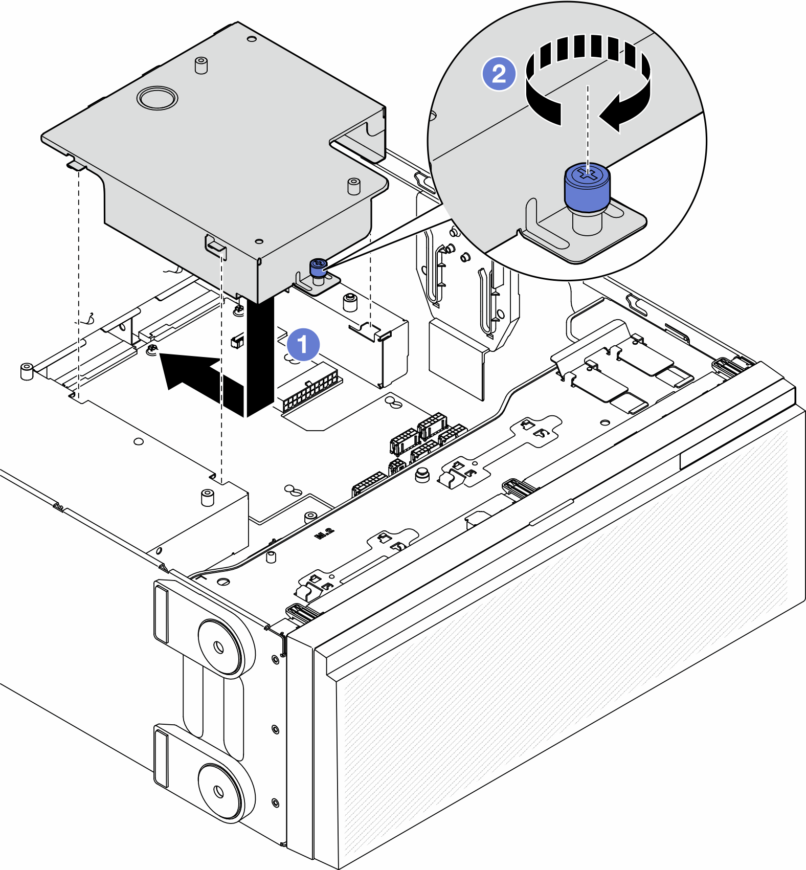
After this task is completed
Reinstall the system board. See Install a system board (trained technician only).
Connect the power distribution board cables to the system board. See Power distribution board cable routing.
Reinstall the processor and the heat sink. See Install a processor and heat sink (trained technician only).
Reinstall all the memory modules. See Install a memory module.
Reinstall the CMOS battery. See Install a CMOS battery (CR2032).
Reinstall the intrusion switch or reconnect the intrusion switch cable to the system board. See Install an intrusion switch.
Reinstall the internal CFF HBA/RAID adapter. See Install an internal CFF adapter.
Reinstall the MicroSD card. See Install a MicroSD card.
Reinstall the RoT module. See Install the Firmware and RoT Security Module.
Reinstall all the PCIe adapters. See Install a HL PCIe adapter.
Reinstall the fan cage assembly. See Install the fan cage assembly.
AttentionAll fan modules must be removed from the fan cage when handling the fan cage assembly.Reinstall all the fan modules (and fan filler, if necessary). See Install a fan module.
Install the required A2/L4 GPU air ducts or FL PCIe adapter holders. See Install an A2/L4 GPU air duct and Install a FL PCIe adapter holder.
Reinstall all the full-length GPU adapters, if necessary. See Install a FL GPU adapter.
Reconnect all the cables that were removed. See Internal cable routing.
Reinstall the air baffle. See Install an air baffle.
Reinstall all the flash power modules, if necessary. See Install a flash power module.
Reinstall the server cover. See Install a server cover.
Reinstall the redundant power supply unit. See Install a power supply unit.
Complete the parts replacement. See Complete the parts replacement.
Update the vital product data (VPD). See Update the Vital Product Data (VPD).
Machine type number and serial number can be found on the ID label, see Identify the server and access the Lenovo XClarity Controller.
If hiding TPM or updating TPM firmware is needed, see Hide/observe TPM or Update the TPM firmware.
Optionally, enable Secure Boot. See Enable UEFI Secure Boot.
Demo video